Auto electronics
Informationalized Solution
R&D tools
Marketing

Overview
Intelligent connected vehicles utilize technologies such as computers, modern sensors, information fusion, pattern recognition, communication networks, and automatic control. They integrate environmental perception, planning and decision-making, and multi-level autonomous driving control into a comprehensive technology complex. Consequently, testing and validation in the development of intelligent connected vehicles face significant challenges. On one hand, new testing methods are needed to improve traditional road test methods, addressing issues caused by the need for extensive mileage in conventional tests. On the other hand, due to the limited market penetration during the initial development stages, the testing and verification process must also consider the significant impact of other road users' driving behavior on autonomous vehicle functions in a mixed traffic environment.
Polelink collaborates with renowned domestic and international enterprises to provide Chinese automotive clients with intelligent driving-related test systems and services. These include MiL/HiL/ViL test systems for L1-L5 autonomous driving control systems, data collection and real vehicle functional testing for autonomous driving, millimeter-wave radar testing, and simulation systems, comprehensively assisting the research, development, and production of intelligent connected vehicles.
With technological advancement, the mass production of autonomous driving technology in vehicles has evolved from basic L1/L2 assisted driving to L3 and even higher levels. Advanced autonomous driving technology relies on more sensors, increasing testing challenges in environmental perception, multi-sensor fusion, decision-making and planning, vehicle control execution, and functional safety.
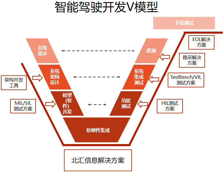
As a leading test solution provider in China, Polelink offers solutions at various stages of research and development for OEMs, control system/sensor suppliers.
Intelligent Driving Simulation Testing: MiL/SiL/HiL/ViL
According to a study by the RAND Corporation, autonomous driving requires driving billions or even trillions of miles to verify its reliability, which would take decades or even hundreds of years to complete through real vehicle driving. Additionally, the N-FOT project in the US found that "the cost of completing a public road test is at least $1 million."
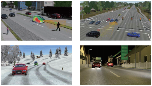
Considering time and cost, virtual simulation technology allows for the simulation modeling of road environments, traffic, perception systems, decision-making and planning systems, and execution systems in a laboratory environment, accelerating intelligent driving R&D. Compared to traditional simulation testing, intelligent driving simulation testing demands higher accuracy in vehicle dynamics simulation, focusing more on vehicle-environment interaction, test scenario analysis, and test scenario database construction.
MiL/SiL Solutions
MiL/SiL testing primarily tests the functional logic of algorithm models. Polelink based on mainstream virtual simulation software (e.g., Hexagon's VTD, Vector's DYNA4 and CANoe) and automated testing tools (e.g., Synopsys's TPT, Vector's vTESTstudio), provides comprehensive intelligent driving MiL/SiL solutions. These cover MiL/SiL testing of decision-making and planning control algorithms such as AEB, LDW, TSR, HMA, LCDA, LKA, IACC, TJP, TJA, and APA, as well as sensor fusion algorithm MiL/SiL testing.
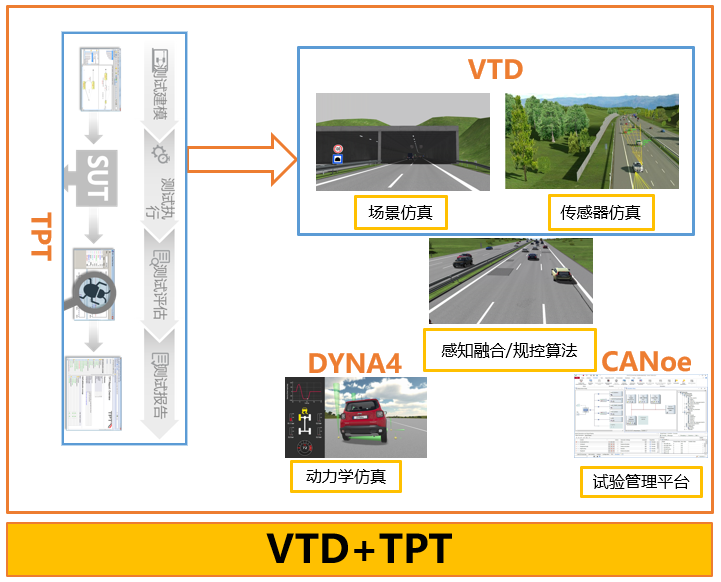
VTD, as a commercially professional virtual scene simulation software, achieves realistic scene rendering, high-precision sensor models, and surrounding traffic flow simulation. Combined with Vector's mainstream DYNA4 dynamics software and CANoe test management software, it completes the dynamic closed-loop and various model/middleware interface adaptation required for intelligent driving MiL/SiL, ensuring good consistency and real-time data interaction during the testing process.
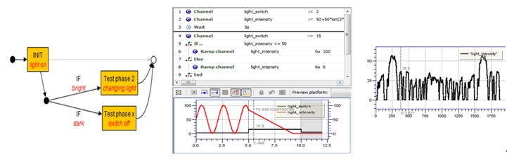
TPT provides an efficient test modeling method, capable of controlling the parameter inputs of various virtual scene elements and automating the entire process from test execution to report generation.
Intelligent Driving Smoke Testing Solutions
Introducing smoke testing in intelligent driving testing maximizes the reduction of testing costs, improves software development and testing execution efficiency, ensures software quality, and reduces testing risks. Polelink provides a self-developed test management platform, PAVELINK.TestCenter, offering functions such as controller software version management, online software flashing, test task planning, execution, and automatic report sending.
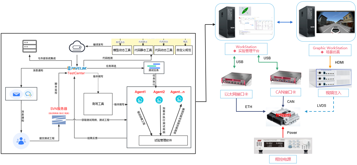
In the smoke testing solution, the controller and bench's simulated peripheral environment form a closed loop. The test management software CANoe manages the bench's power control and bus simulation environment. After software version updates, PAVELINK.TestCenter completes automated flashing, and CANoe and vTESTstudio execute the automated smoke test plan. Finally, the automated report is sent back. Smoke test results can also be sent to software development and testing personnel via email or DingTalk, addressing testing efficiency issues and late detection of software defects caused by version iterations. The testing framework is as follows:
HiL Solutions
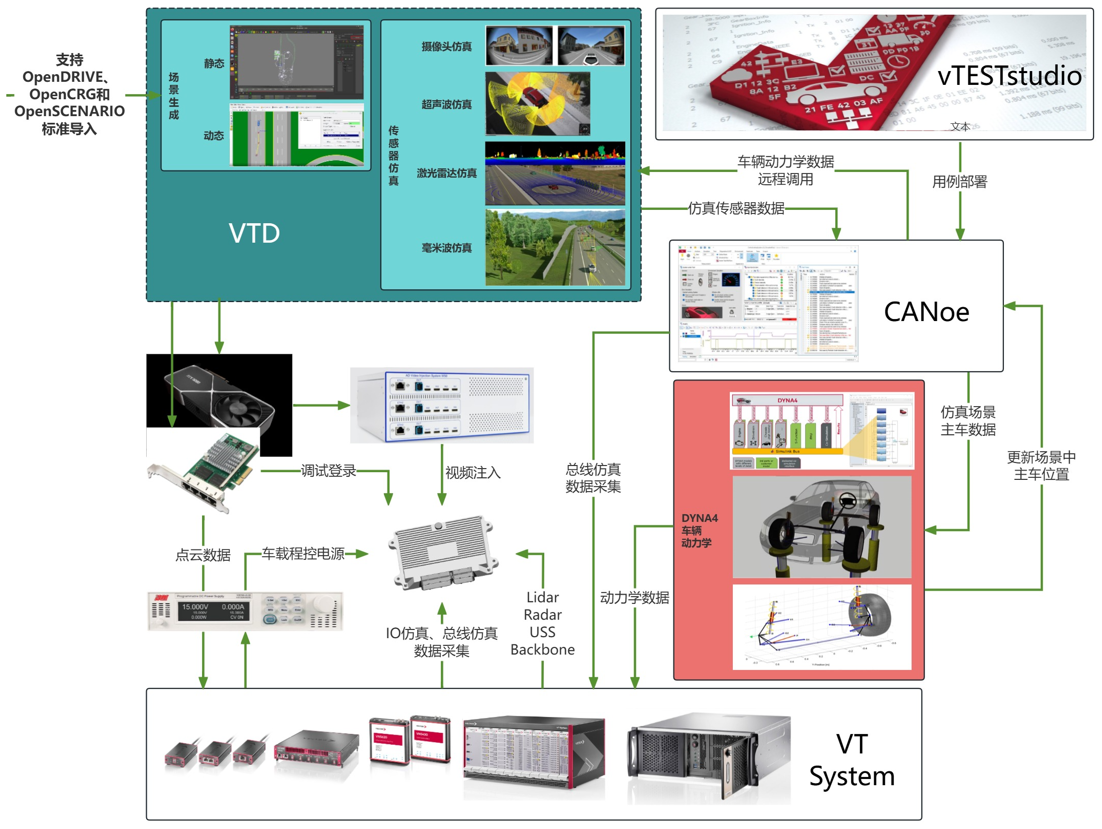
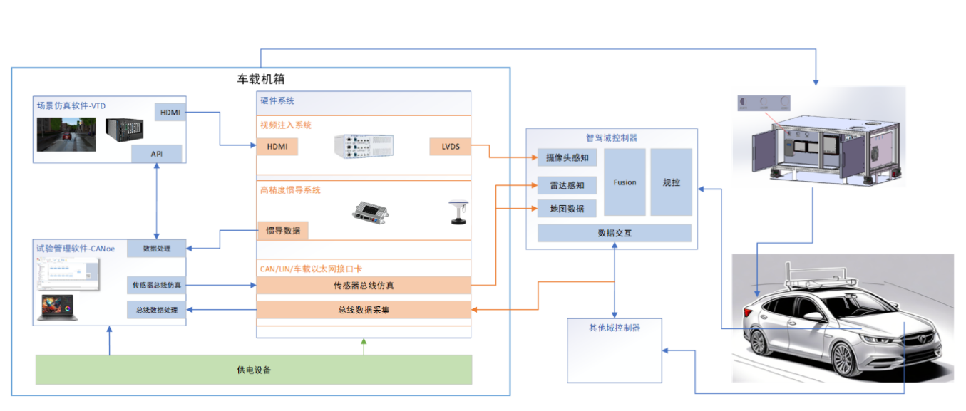
Polelink, based on mainstream virtual simulation software VTD, Vector HiL hardware platform, and cost-effective radar simulators, provides HiL solutions including radar simulation, video stream data injection, ultrasonic simulation/data injection, and LiDAR point cloud simulation. Combined with VT I/O cards and VN series bus simulation systems, Polelink offers high-precision, user-friendly, and highly integrated automated HiL test solutions. Solutions also include intelligent driving with multi-degree-of-freedom driving simulators, intelligent driving with chassis/cabin/power and other multi-domain HiL solutions, covering single intelligent domain control to cross-domain control HiL testing. The intelligent driving HiL testing framework is as follows:
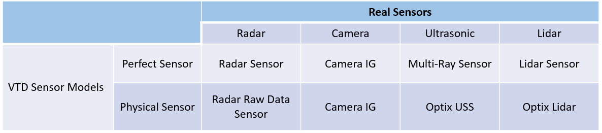
In HiL testing solutions, Polelink provides multi-level sensor simulation methods based on different testing needs and objects. We offer precise sensor models (based on target information lists and physical sensor models) and support secondary development based on SDKs.
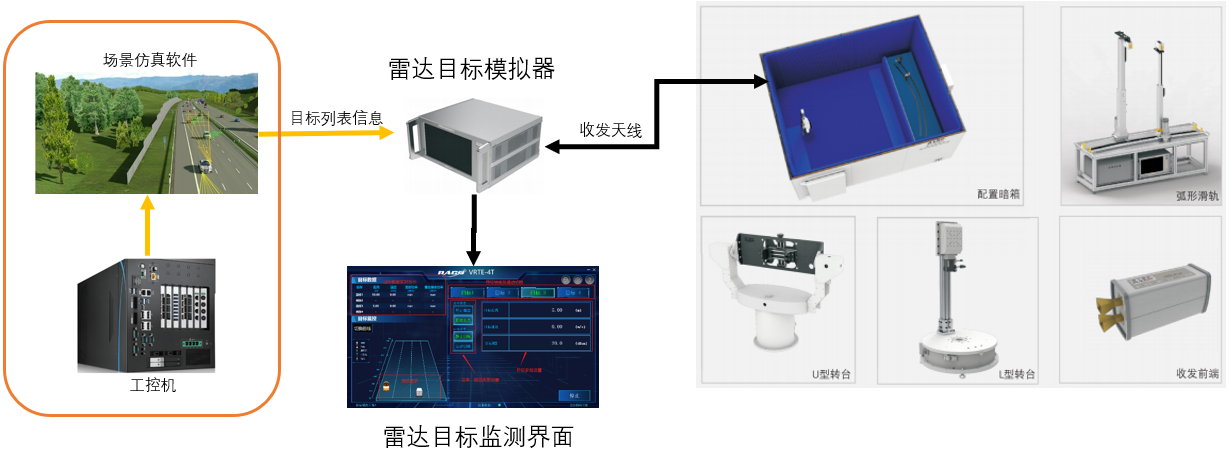
Millimeter-Wave Radar Echo Simulation Solutions
Based on radar target simulators from Polelink's partners, we provide various combined radar echo simulation solutions, including single-direction 4 targets, dual-direction 8 targets, and over 1000 points echo simulation (based on 4D imaging radar). Product features:
- Simulate point targets and 4D point cloud targets
- Range: 24/60/77/79/92GHz
- Distance range: 0~3000m
- Speed range: ±720Km/h
- Angle range: customizable
- RCS dynamic range: 90db
- Simulate opposite car interference
- Combine with virtual scene simulation for millimeter-wave radar in-loop functional testing (e.g., ACC/AEB)
- Simulate real intersections, cars merging, road slopes, crossroads
- Simulate road scenes such as obstacles, height restrictions, various weather conditions
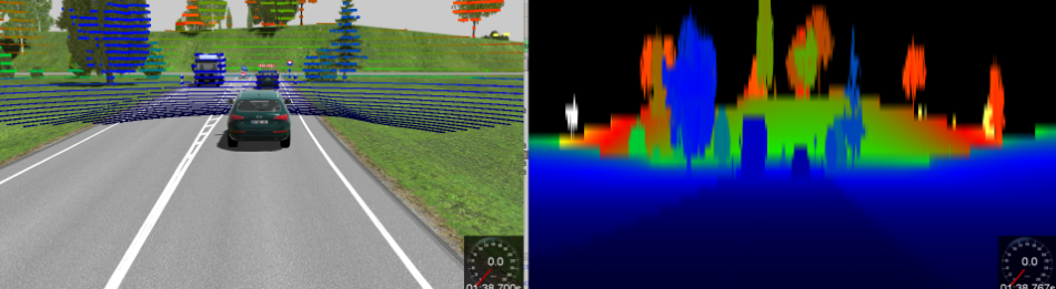
Millimeter-Wave Radar Data Stream Simulation Solutions
Using ray tracing to simulate the propagation of electromagnetic radar waves, achieving full real-time simulation. Product features:
- Simulate 4D millimeter-wave point clouds
- Multi-path propagation
- Repeat path echoes
- Doppler shift
- False alarm simulation
Camera Data Stream Injection Simulation Solutions
By using video injection boxes to convert the virtual scene's simulated camera data stream into video data streams recognizable by intelligent driving domain controllers, we provide image processing-related intelligent driving application tests. This method offers a more realistic image source than using camera dark boxes and is suitable for multi-channel camera simulation solutions. Product features:
- Support simultaneous simulation of 12 camera signals (front view, surround view, bird's eye view, rear view)
- Maximum resolution per camera exceeds 1080P
- Frame rate not less than 60 FPS
- Support for camera signal color spaces (RGB, YUV, RAW, etc.)
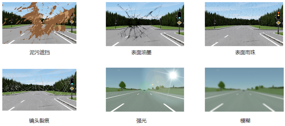
- Combine with scene simulation software to simulate camera fault injection, including lens occlusion, cracks, strong/weak exposure, motion blur, etc., for ISO26262 compliant intelligent driving functional safety tests
Ultrasonic Radar Simulation Solutions
Simulate ultrasonic echoes based on the transducer characteristics of ultrasonic sensors. Using virtual ultrasonic sensors from scene simulation software, we obtain obstacle distance and angle information. The ultrasonic simulation board card drives the transducer to generate ultrasonic echoes, which real ultrasonic probes detect and inject the echo information into the parking controller to verify automatic/remote/controlled parking functions. Ultrasonic simulation also supports ultrasonic hardline transmission protocol simulation. Product features:
- Support simulation of 12 ultrasonic channels
- Adjustable ultrasonic reflection time for each sensor
- Support transducer drive and hardline simulation modes
- Frequency range 20-100kHz
- Simulation distance range 0-10m
- Support single reception and transmission, single reception multiple transmissions
ViL Solutions
In vehicle-in-loop (ViL) testing, real vehicles provide a genuine dynamic environment. We only need to simulate various test scenarios and traffic flows around the vehicle using scene simulation software. Polelink combines intelligent driving sensor simulation technology to provide vehicle-in-loop solutions for automatic parking, driving, etc.
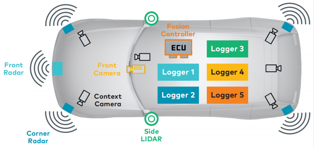
Real Vehicle Testing Solutions
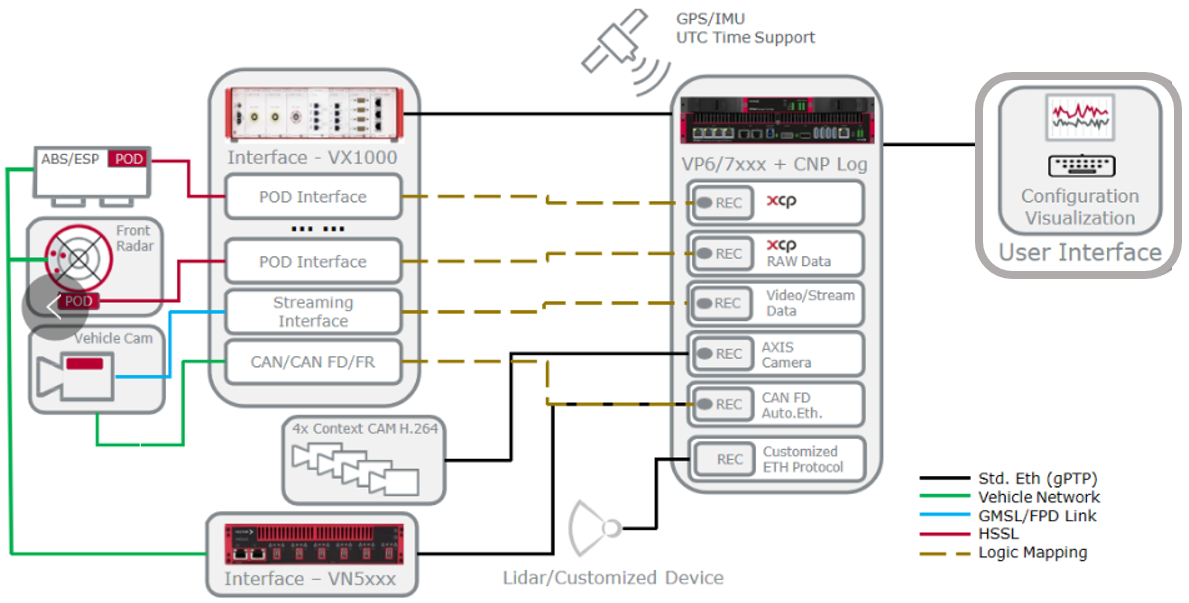
Real vehicle road testing is a crucial step in the development of intelligent driving vehicles. Road testing allows for the real evaluation of various sensor systems and autonomous driving functions' performance indicators. Based on Vector's CANape software, VP series hosts, and various bus acquisition devices, Polelink offers a comprehensive solution for intelligent driving road test data collection, capable of synchronously collecting real vehicle operation data and various sensor data.
![]()
![]()
![]()
![]()
![]()
© 2022 Shanghai PoleLink Information ICP-Licence:沪ICP备14018904号-1