中文  |  English
Home > Auto electronics > BMS HiL solution

BMS HiL solution

The Battery Management System (BMS) is a critical component in electric vehicles, serving as the core of the key technology for monitoring and protecting the normal operation of the entire vehicle. Its main functions are the intelligent management and maintenance of individual battery cells, including real-time monitoring of battery physical parameters, battery state estimation, preventing battery overcharge and over-discharge, prolonging battery life, online diagnosis and early warning, balancing management, and thermal management.

In a Hardware-in-the-Loop (HIL) testing environment, the actual battery pack is simulated using equipment such as battery emulators and power supplies. This allows for the rapid simulation of different single-cell states, environmental conditions, and fault conditions that are extremely difficult to achieve in real-vehicle testing, enabling fast and comprehensive functional testing of the BMS.

Furthermore, the HiL testing environment can effectively shorten the R&D and testing cycle through parallel testing and 7x14 hours of unattended testing.


I. Relevant Standards

  • GB/T 38661-2020 Technical Specifications for Battery      Management Systems for Electric Vehicles
  • GB/T 18487.1-2023 Conductive Charging System for Electric      Vehicles Part 1: General Requirements
  • GB/T 27930-2015 Communication Protocol between Off-board      Conductive Charger and Battery Management System for Electric Vehicles      
  • GB/T 27930-2023 Digital Communication Protocol between      Off-board Conductive Charger and Electric Vehicle
  • GBT 27930.2-2024 Digital Communication Protocol between      Off-board Conductive Charger and Electric Vehicle Part 2: Communication      Protocol for GBT20234.3
  • GB/T 34658-2025 Communication Protocol Conformance Test      between Off-board Conductive Charger and Battery Management System for      Electric Vehicles


II. Solution Composition

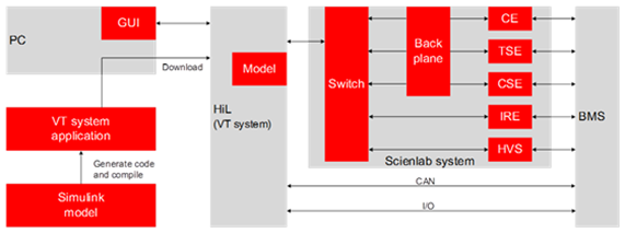
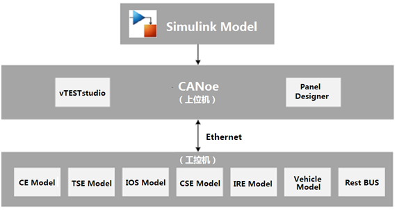
The software part of the BMS HiL test system provided by Beihui Information mainly includes CANoe and vTESTstudio. CANoe serves as the control and execution software for the entire test system, implementing automated closed-loop testing of the BMS controller. vTESTstudio is used for writing test cases and performing automated testing.

 bms图 .png

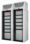
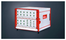
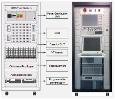
The hardware part mainly includes: a real-time processor, general IO board (VT board), bus communication board, battery emulator, current sensor simulation board, high-voltage power supply, insulation resistance simulation board, and fault injection board.

  • Real-time Processor: Runs the BMS      battery model and residual bus model.
  • VT Board: Provides the IO input      signals required by the BMS and collects the IO output signals from the      BMS.
  • Bus Communication Board: Provides      the CAN/CANFD and LIN bus channels required by the BMS.
  • Battery Emulator: Provides the      single-cell voltage and temperature simulation required by the BMS.
  • Current Sensor Simulation Board:      Provides Hall or Shunt type current sensor simulation.
  • High-Voltage Power Supply: Provides      the total voltage simulation required by the BMS.
  • Insulation Resistance Simulation Board: Provides the insulation resistance between the BMS battery      pack and the vehicle body.
  • Fault Injection Board: Provides      fault simulation for the corresponding IO channels of the BMS, including      short circuit, open circuit, short to power, short to ground, and      inter-wire short circuit.

Battery Model:

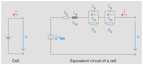
A second-order RC battery model built on Simulink, which can reflect the dynamic characteristics and polarization phenomena of the battery. It has three initial modes: global setting of SOC and temperature for all cells, global setting of OCV and temperature for all cells, and individual modification of OCV for specific cells. It also includes initial value look-up table modules for equivalent impedance and OCV, as well as different shunt circuits for charging and discharging.

Charging Model:

The power battery charging model is compatible with the relevant processes and parameter requirements of national standards GB/T 27930-2011, GB/T 27930-2015, GB/T 27930-2023 and GB/T 27930.2-2024. The DC charging model supports simulating the charging connection, simulating the charging CC2 resistor signal, correctly simulating the relevant messages for the national standard charging connection, handshake, parameter configuration, charging, and end processes, and achieving automatic interaction with the BMS28. The AC charging model can simulate the charging connection, simulate the CC resistor signal and CP frequency duty cycle signal, achieve control of the charging voltage and current, and interact with the BMS to complete the charging process simulation.

The solution supports the extension of European and American standard charging models, including DIN70121 and ISO 15118 protocols.


III. Typical Test Scenarios

BMS typical test scenarios:

  • Signal acquisition: single-cell voltage, single-cell      temperature, total voltage measurement, current measurement
  • Energy estimation: SOC, SOH
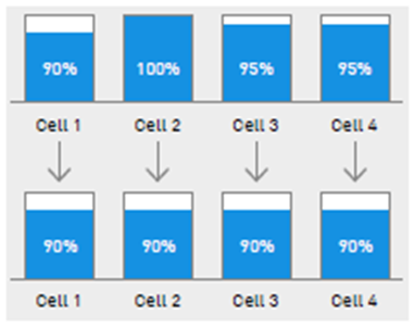
  • Balancing function
  • Charging management
  • Insulation detection
  • Thermal management control
  • Battery fault detection and alarm
  • Communication function
  • Functional safety


IV. Solution Features

The BMS HiL test system provided by Beihui Information:

  • Supports functional testing, fault diagnosis, and can be      extended for network testing and diagnostic flashing tests.
  • Can simulate extreme operating conditions and electrical faults.
  • Modular VT board is easy to expand and reuse.
  • CANoe's rich hardware and software interfaces support the      integration of third-party hardware and software.
  • Based on Beihui Information's extensive experience in building      and servicing test systems, a true turnkey system is provided.