Auto electronics
Informationalized Solution
R&D tools
Marketing
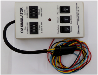
The Oxygen Sensor Signal Simulator is designed for use in the calibration of the electrical control system of gasoline-running machines. It can simulate the actual oxygen sensor in the scenario of all kinds of breakdowns, including but not limited to faulty connections, loss of detector sensitivity, etc. It can be used to simulate faulty oxygen sensor readouts to aid in the testing and diagnosis of gasoline operated vehicles.

To best imitate oxygen sensor failure, the simulator creates a response by modifying the signal from the actual electric control system. Thus, the simulator needs to be input a normal oxygen sensor signal, which acts as a basis from which the device simulates a fault.
Bypass/Simulate
When the device is set to ‘Bypass’, the signal directly returns to the ECU without modification. When the device is set to ‘Simulate’, the signal is modified in accordance with the mode of choice and control parameters, and then output to the ECU.
Mode Selection
In order to simulate various types of sensor failure, there are 3 different modes that the device can be set to:
Mode 1. Positive Deviation:
In this mode, after the signal is converted to a digital value by the A / D converter, it is modified by the user set attenuation factor and increased by the offset value before being output through the D / A converter.
The output signal (D / A) = input signal (A / D) × attenuation factor (0.0 ~ 0.999) + deviation value (0 to 999mV).
Mode 2. Negative Deviation:
In this mode, after the signal is converted to a digital value by the A / D converter, it is modified by the user set attenuation factor and decreased by the offset value before being output through the D / A converter.
The output signal (D / A) = input signal (A / D) × attenuation factor (0.0 ~ 0.999) - deviation (0 to 999mV).
Mode 3. Kup/Kdown:
This mode simulates the oxygen sensor’s delayed response. The simulator applies either the positive or negative “filter” to the signal depending on whether the signal is in its increasing or declining phase, respectively.
When the Kup/Kdown factor is set at 999, there is basically no effect. When the factor is smaller, the effect is larger. The internal generator selects the corresponding delay in the sensor’s response time based on the set factor.
Signal increasing phase:
The output signal (D / A) = previous output signal x (1-filtering value) + x (the positive input value: 0.0 ~ 0.999)
Signal declining phase:
The output signal (D / A) = previous output signal x (1-filtering negative value) - y (the negative input value: 0.0 ~ 0.999)
Resistance/No Resistance:
To ensure that the device accurately simulates the different types of oxygen sensors, there is the option to turn on or off internal resistance. This switch allows you to simulate generators with internal resistance (487K ohms). If there is no resistance, keep the switch in the "abolish pull" position.
Note: The reason the resistance simulator is necessary is: the ECU system can normally provide the necessary current. However, in the process of connecting the O2 Sensor Signal Simulator, the high voltage signal current was interrupted. Thus, additional current must be provided to maintain normal operation. The role of this electric current is to ensure pristine gas detection by the sensor.
 Quick links
 Detailed consultation